Hoxter ABRA 6 Fireplace Control
 | |
|---|---|
| Frequencies | 433.219 MHz |
| Frequency Range | 433.219 MHz - 433.219 MHz |
| Mode | FM |
| Modulation | FSK |
| ACF | — |
| Bandwidth | 6 kHz |
| Location | Europe |
| Short Description | Digital transmission of temperature and status of HOXTER fire-burning control ABRA 6. |
| I/Q Raw Recording | Download file |
| Audio Sample | — |
Digital transmission of temperature and status of HOXTER fire-burning control ABRA 6.
This is the recording of my unit at 433.219MHz, using one out of 9 channels.
I found a transmission of 10ms length every 100ms.
It seems, that "rawIQ" is more useful, but I have no clue of what modulation is used. The unit transmits a temperature (at least 0..999 degree), a runtime (0:00..4:00 = max. 240 minutes?) and a status of at least 6 runtime states and 3 alarm states. During initial configuration the transmitter seems to be able to freely access the 4-digit alpha-numeric display, but that's not important at this time.
The problem is: I do not know which demodulation to use to get some bits out of it. I don't even know the bitrate and whether each transmission every 100ms is valid on its own, or if they only contain 1 byte giving a transfer rate of 10 bytes per second... I made a screenshot of the saved audio files and tried to convert the raw data from 3200000 samples/second to 48000 samples/second:
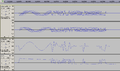
Demod comparison

I also uploaded the demodulation of GQRX using "rawIQ" and "AMAmplitude Modulation" as "I/Q Raw Recording".
After some research I found that FMFrequency Modulation decoding the signal is much more usable. It does not seem so on the first sight, because there was much noise in idle times. Reducing the scan rate also reduced the noise a little and for some reason gained the correct signal:

NFMNarrowband Frequency Modulation demodulated signal
It shows nice the TTL level of 32 bits preamble (01) and some more bits of hopefully useful data. I compared some signals over time and found that there are always 6 fixed bytes at the beginning: 2D.D4.46.49.52.45 Then follows 1 byte for the current status, 2 bytes for temperature, 1 byte for current hour, 1 for minutes and another still unknown which is always 0. At the end there are 2 bytes of CRC. This was a pure guess at the beginning, but probing some byte combinations in some Online CRC calculator showed, that it is a "CRC-CCITT (XModem)" code for all bytes after the first 2 (2D.D4).
Again: I did not know much about FSKFrequency-Shift Keying modulation that time and tried to find a simple transceiver that is able to read that signal. During my research I found, that HopeRF's RFM12(b) and also the contained Silicon Labs Si442x use a default start word of 0x2DD4! I think, the best guess is, that this is the actual chip that is used to produce that signal.
Unfortunately, I don't know how to identify bandwidth and deviation... But I hope these pictures help others to identify FSKFrequency-Shift Keying signals, if they do not know anything about the received signal!