Automatic Picture Transmission (APT)
 | |
|---|---|
| Frequencies | 137.1 MHz,137.62 MHz,137.9125 MHz |
| Frequency Range | 137.1 MHz - 137.9125 MHz |
| Mode | AM, FM |
| Modulation | AM,FM |
| ACF | — |
| Emission Designator | — |
| Bandwidth | 34 kHz |
| Location | Worldwide |
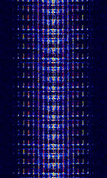
| Short Description | Automatic Picture Transmission (APT), also known as NOAA-GEOSAT, was an analog image transmission mode used by the NOAA weather satellites and some Russian weather satellites to transmit satellite weather photos. As of august 2025, most of the NOAA sats that transmitted this mode have been decommissioned, and have discontinued transmission. |
| I/Q Raw Recording | Download file |
| Audio Sample | |
Weather Satellite Modes: APT - LRPT - Meteosat WEFAX
Automatic Picture Transmission (APT), also known as NOAA-GEOSAT, is an analog image transmission mode used to by the NOAA weather satellites and formerly some Russian weather satellites to transmit satellite weather photos. On August 19th 2025, the final satellite transmitting this mode (NOAA-15) was decommissioned at 15:26 UTC. This mode is no longer in use.
Characteristics[edit]
Structure[edit]
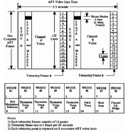
The broadcast transmission was composed of two image channels, telemetry information, and synchronization data, with the image channels typically referred to as Video A and Video B. All this data was transmitted as a horizontal scan line. A complete line is 2080 pixels long, with each image using 909 pixels and the remainder going to the telemetry and synchronization. Lines were then transmitted at 2 per second, which equates to a 4160 words per second, or 4160 baudBaud (unit symbol Bd) is the unit for symbol rate or modulation rate in symbols per second..
| Name | Length in pixels | Description |
|---|---|---|
| Sync A | 39 | Bits 000011001100110011001100110011000000000 |
| Space A | 47 | |
| Image A | 909 | Image pixels, a higher amplitude results in a brighter pixel |
| Telemetry A | 45 | |
| Sync B | 39 | Bits 000011100111001110011100111001110011100 |
| Space B | 47 | |
| Image B | 909 | Image pixels, a higher amplitude results in a brighter pixel |
| Telemetry B | 45 | |
| Total | 2080 / 0.5 seconds |
Images[edit]
On NOAA POES system satellites, the two images are 4 km / pixel smoothed 8-bit images derived from two channels of the advanced very-high-resolution radiometer (AVHRR) sensor. The images are corrected for nearly constant geometric resolution prior to being broadcast; as such, the images are free of distortion caused by the curvature of the Earth.
Of the two images, one is typically long-wave infrared (10.8 micrometers) with the second switching between near-visible (0.86 micrometers) and mid-wave infrared (3.75 micrometers) depending on whether the ground is illuminated by sunlight. However, NOAA can configure the satellite to transmit any two of the AVHRR's image channels.
Synchronization and telemetry[edit]
Included in the transmission are a series of synchronization pulses, minute markers, and telemetry information.
The synchronization information, transmitted at the start of each video channel, allows the receiving software to align its sampling with the baudBaud (unit symbol Bd) is the unit for symbol rate or modulation rate in symbols per second. rate of the signal, which can vary slightly over time. The minute markers are four lines of alternating black then white lines which repeat every 60 seconds (120 lines).
The telemetry section is composed of sixteen blocks, each 8 lines long, which are used as reference values to decode the image channels. The first eight blocks, called "wedges," begin at 1/8 max intensity and successively increase by 1/8 to full intensity in the eighth wedge, with the ninth being zero intensity. Blocks ten through fifteen each encode a calibration value for the sensor. The sixteenth block identifies which sensor channel was used for the preceding image channel by matching the intensity of one of the wedges one through six. Video channel A typically matches either wedge two or three, channel B matches wedge four.
The first fourteen blocks should be identical for both channels. The sixteen telemetry blocks repeat every 128 lines, and these 128 lines are referred to as a frame.
Broadcast signal[edit]
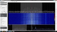
The signal itself is a 256-level amplitude modulated 2400Hz subcarrier, which is then frequency modulated onto the 137 MHzMegaHertz (MHz) 10^6 Hz-band RFRadio Frequency carrier. Maximum subcarrier modulation is 87% (±5%), and overall RFRadio Frequency bandwidth is 34 kHzKiloHertz (kHz) 10^3 Hz. On NOAA POES vehicles, the signal is broadcast at approximately 37dBm (5 watts) effective radiated power.
Frequencies[edit]
NOAA 15 - 137.620 MHzMegaHertz (MHz) 10^6 Hz
NOAA 19 - 137.100 MHzMegaHertz (MHz) 10^6 Hz
Decoding Software[edit]
- Hobby Level Software
- SatDump
- MultiPSK
- apt-decoder
- noaa-apt
- SatSignal
- SDRangel
- aptdec (formerly atpdec)
- WxtoImg (Abandonware)
Encoding Software[edit]
Decoding Tutorials[edit]
Antennas[edit]
The NOAA satellites that downlink APT signals transmit with a right-hand circularly polarized (RHCP) quadrifilar helical antenna (QFH). Using an RHCP QFH to receive these signals is a good idea, as the polarization will be the same and the antenna has a very wide beamwidth. Other popular choices that are circularly polarized are the turnstile and double cross dipole antenna.
Another option is a v-dipole. Though it is linearly polarized, the polarization mismatch loss is typically insignificant and easily ignored. This antenna uses two legs roughly 54cm long spread 120° apart at the feed point. This forms a 'V' shape, with the feed point (where the coaxial cable connects) at the bottom corner where both legs meet. This v-dipole is more directional than the previously mentioned antennas so it must be positioned properly. Point the antenna so that the legs are parallel to the ground, and a line bisecting the angle between the legs points North or South, it doesn't matter which. The height above the ground matters for this antenna. Heights that are multiples of half the wavelength should be avoided, so ~1m, ~2m, ~3m, etc due to nulls directly overhead. The best height is somewhere between 0.4m and 0.8m, anything higher will introduce nulls and dips in the radiation pattern. If the antenna needs to be placed higher, say above a tree line or buildings, then a reflector may be placed 0.4-0.8m below it for the same benefit. A reflector can be as simple as another v-dipole with slightly longer legs.
Permanent ground stations may wish to opt for the QFH or turnstile so that lower-elevation passes can be received. For single-pass captures or for mobile ground stations, v-dipoles are very good options as they are portable and offer more gain on high elevation passes.
Video Examples[edit]
- How to take NOAA satellite pictures using RTL-SDR for under 50$
- RTL-SDR 2832U A RECEBER NOAA-18 EM 20SET2012 14H UTC CT1ETK
- Receiving NOAA weather satellite using SDR# and WXtoImg
- RECEIVING NOAA 19 RTL-SDR APT DECODE, SDRSHARP, WXTOIMG, ORBITRON, AUTO-DOPPLER
- Weather Satellite NOAA 18 received with RTL2832, SDR# and WXtoimg
Additional Links[edit]
- RadioScanner.RU NOAA APT
- Wikipedia Automatic Picture Transmission
- WAVECOM Database: NOAA Geosat (APT)


